Powermatic Model 221 Planer
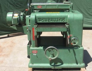
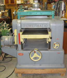
The Powermatic Model 221 planer. Thousands of school, millwork and pattern shops, as well as hundreds of high production plants throughout America have discovered that the Powermatic Model 221 planer is unsurpassed for dependable, precision performance in an extremely wide variety of planing requirements. It incorporated every modern safety and operations feature for maximum efficiency.
Powermatic Model 221 Planer Features

Frame: Precision machined from extra heavy cast iron. Extra wide side panels with gibs offer rigid bed support and perfect alignment. One piece 34" x 44 3/4" cast iron base.
Bed: 20 1/8" x 40", accurately machines with extra heavy rib-reinforcing for perfect alignment and maximum strength. Bed raises and lowers no large acme-thread screws, mounted on enclosed thrust bearings.
Convenient hand wheel adjusts bed through full 8" range with 1/16" movement upon each complete turn. Adjacent front-mounted gauge is calibrated for quick, easy reading.
Powermatic Model 21 Planer Cutterhead: Safety-type, milled from carbon tool steel and fitted with 3 high-speed knives, 5/32" x 1 1/4" x 20". Mounted in over-size, sealed bal bearings, the entire cutterhead unit may be lifted free by removing feed drive pulley and locking screws from flange mounting. 4 1/4" cutting circle.
Powerating speed is 4600 RPM (belted) with 13,800 cuts-per-minute (50 knife cuts per inch) at 20 feet per minute feed rate. Direct drive operating speed of 3600 RPM yields 10,800 cuts-per-minute (40 knife-cuts-per-inch) at 20 feet-per-minute feed rate.
Feed Rolls: Milled from tool steel. Extra large 4: in diameter with mounting yield of 1/4". Mounted in sealed-for-life ball bearings and plunger-type coil springs. Feed rolls fully reversible on 3-phase current only.
Infeed roll: corrugated, solid type is standard. Sectional type optional.
Outfeed roll: smooth 4" diameter, solid type with two adjustable, 2 3/4" table idler rollers. Fully adjustable, with drive through over-size cut gears by V-belts from cutterhead spindle.
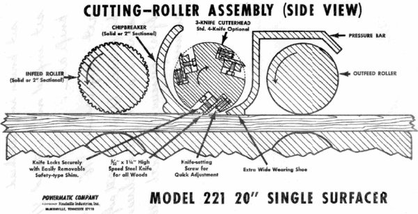
Pressure Bar: Mounted concentric to cutterhead and fitted extremely near knife cutting circle. The bar has extra wide foot for long wear and can be adjusted while machine is in operation.
Chipbreaker Solid Type: Swings concentric to cutterhead and mounted just forward of the knife-cutting circle. Has 3/8" yield with extra wide, accurately machined oot to assure longer wear and top grade finishing.
Power Feed Control: Variable speed pulley affords complete range of feed from 20 to 50 feet-per-minute. Driven by 1 HP totally enclosed motor mounted in base. Controlled by side mounted instantly reversing drum switch.
Stock Capacity: Surfaces stock up to 20" wide and from 1/8" to 8" thick.
Guards: designed for complete operating safety, guards enclose all moving parts, Easily removed for quick access.
Lubrication: All bearings either sealed for life type or equipped with easy to reach Alemite fittings.
Drives: Belted drive (Model 221-B) cutterhead is driven by motor mounted directly to cutterhead shaft.
Power: 5 HP motor is recommended for light and medium work loads for the Powermatic Model 221 Planer. For heavier requirements and high production use, the 7 1/2 or 1- HP motor is recommended.
Electricals: Machine standard equipped with magnetic controls protecting both feed and drive motor. With this exclusive safety feature, both motors shut off instantly after power failure.
Powermatic Model 221 Planer Operating Instructions:
Powermatic Model 221 Planer Bed:
The planer bed mounts in the main frame panels and is held rigid by the shims and adjusting screws located in front of machine. The bed is raised and lowered by the gears and thrust screw operated by the large hand wheel on fronT of machine. Keep shims adjusted to hold the planer bed rigid in ways but not tight enough to restricT freedom of raising and lowering with hand wheel. The planer bed must be level with cullerhead. Check this by lowering the bed to allow placing a small jackscrew type gouge (or small square block) between one extreme end of cutterhead. Slide the gouge to opposite end of cutterhead to determine if the some measurement exists. If the bed is out of level, adjust in the following manner. Loosen set screw (3) that locks adjusting nut (4) in bed. Turn nut (4) to the right or left to raise or lower the bed in the desired amount. and lock in place with set screw (3).
Planer Bed Idler Rolls:
The bed rollers (2) Fig. 2 are adjusted to proper height with a "quckset" handle mounted on right hand side of planer bed. The height of the rollers in relation to table surface is indicated by a graduated dial and a pointer on the "quickset" handle. If the table roller height does not correspond with height indicator scale adjustment can be made by: Loosening the set screws (1) Fig. 2 in the roller adjusting arms. Set the indicator pointer at zero on the gauge and turn adjusting screws until bed rollers are level with the planer table. Tighten the set screws in adjusting arms. To plane rough sawn lumber, the indicator should be set on .030 inches. For medium rough, .010 to .015 and for fine finish, .00 to .010. Set rollers high enough that the lumber will feed through the machine without hesitation.
Planer Bed Handwheel Drive Assembly:
The planer bed thrust screws are powered by the gears and hand wheel arrangement and do not require any adjustment other than keeping gears in proper mesh and tight on hand wheel drive shaft.
Power Driven Feed Rollers:
The Powermatic Model 221 Planer uses two feed rollers. The sectional infeed roller (6) Fig. 3 and smooth outfeed roller (5) are driven with roller chain and sprockets from 1 HP motor mounted in base of machine. The rollers are mounted on sealed ball bearings that require no lubrication. The rollers are mounted in floating type bearing boxings that are held down with pressure springs on top that can be regulated with adjusting screw (10) Fig. 4. The height adjustment of the feed rollers (from the bed) are adjusted with set screws (7) Fig. 3. The feed rollers should be approximately 1/8" lower than the arc cut of the cutterhead knife. A Jackscrew type gauge or a square block should be used to set the rollers. The feed roller pressure springs should be adjusted by trial and error method to determine necessary pressure for proper feeding. Too much pressure on infeed corrugated roller will leave markings on material if light cuts are being made. Rough sawed and green material will require more pressure than smooth dry material. Adjust to where material will feed steadily without hesitation or slippage of rollers.

Powermatic Model 221 Planer Cutting Roller Assembly
Chip Breaker:
The chip breaker (9) Fig. 4 is sectional type with 2" sections mounted on a spring loaded bar that swings concentric with the cutterhead. The sections have approximately 3/8" yield and should be adjusted with set screws (8) Fig. 4 1/16" below infeed rollers.
Pressure Bar:
The pressure bar is adjusted with adjusting screws (11) Fig. 4 and can be individually adjusted from either end by turning adjusting screws (11) Fig. 4 to the right to lower and to the left to raise. The pressure bar should be set the same height as the arc of the cutterhead knife so there will be a slight pressure on the board as it leaves the cutterhead. If the pressure bar is too high it will cause a dip in the end of the board. If it is too low the board will stick. The spring pressure on the bar is regulated with the lock nuts on the adjusting screws.
Material Thickness Gauge:
To set the indicator on the material thickness scale to indicate properly after changing knives, loosen the screw in the planer bed which holds the brass pointer and set to the thickness the material measures when planed or fed through the machine. The hole which mounts the brass pointer is slotted and will permit proper adjustment.
Cutterhead:
The cutterhead is equipped with three knives held in position with the lock shims and set screws. Knives must be adjusted to set evenly and level in the cutterhead. Before removing knives from cutterhead, the knife gauge should be to knives in order that the height of the knives will not be changed relative to the other parts of the machine. The feed rollers, chipbreaker and hold down bar are adjusted to the arc of the knife cut, and if the height of the knives are raised or lowered, the feed rollers, chipbreaker, and hold down bar should be adjusted accordingly. Knives should not protrude more than 1/8" beyond radius of cutterhead. When replacing knives after sharpening, place the knife slot together allowing the knife to protrude 1/4" to 3/8". Tighten the lock shim set screw in each end just enough to hold knife firmly. Using a hard block of wood the knife can be lightly tapped into slot to proper setting. The feeler type gauge furnished with the machine will permit setting knives accurately, however, a dial type indicator gauge is recommended if finest finish is required. Improper knife setting will cause vibration and leave knife marks on finished material.
Knife Care:
Knives should be kept sharp. The knives do all of the work and they will not do satisfactory work if they are dull. The set of knives are matched and balanced at the factory. When the knives are sharpened, care should be taken that they are kept in balance.
Powermatic Model 221 Planer (page reference)
Powermatic Model 221 Planer Manual
All Other Old Woodworking Tools Articles
|
This site proudly build with Site Build It!


